
Demos▸
6.
Embedded Design
In 2008, I took EEL 5666: Intelligent Machines Design Lab, which was the most difficult and rewarding class I have taken. The class centered around a single final project: build a robot that could perform basic object detection and integrated a special sensor for performing its unique task.
This was not a group project. Every student needed to learn how to source their own parts, build their own circuit boards, create their own custom wiring, design their robot's body, calibrate sensors, control various servos and other actuators, and program their microcontroller to handle interrupts and perform basic object detection/avoidance. For a couple months I was putting in 40-60 hours a week on this class alone. But it all came together nicely in the end, and I was able to enjoy my new robot after successfully demonstrating it capabilities. This report covers many of the details in building the robot, some of which have been summarized below.

Basic Description

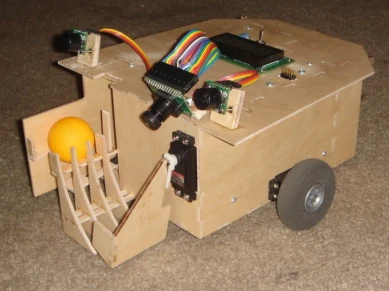
The main function of the robot was to basically play fetch with a ping pong ball. It would roam around the environment looking for a ping pong ball, and after collecting said ping pong ball, return to its base station and pop the ping pong ball up into the air so that I could catch it and throw it, beginning the process anew.
As the robot moved around in search of the ball or base station, it would constantly scan in front of itself using sonar to avoid colliding with any walls or other objects. If it ever worked its way into a corner and started backing into objects, it would randomly try different directions until it had freed itself.
The robot was powered by 8 rechargeable AA NiMH batteries, drove using two wheels, detected the ball and base station using a CMUCam2, detected obstacles using two sonar detectors and bump sensors, and performed all processing on a MAVRIC IIB board
Sensors
The robot used 3 main types of sensors for navigating its environment and completing its objective.
CMUCam2
The robot used the CMUCam2 to locate the ball and base station. The CMUCam2 was capable of performing several on-board pre-processing functions, one of which was blob detection, which would return the size and position of the largest blob of a specified color. Using the fact that ping pong balls are fairly uniquely colored, I could set the search color to bright orange, and then CMUCam2 could report when it saw the ball. Once detected, the robot could approach the ball by using the blob's X coordinate to make sure it was pointed at the ball. To judge distance to the ball, the CMUCam2 was positioned above the robot looking downward so that as the ball got nearer, the Y coordinate would reach the bottom of the view.
Locating the base station used a similar process as with the ball. Conveniently, standard orange mailing envelopes come in a similar orange as ping pong balls, so the same blob detection function could be used unchanged. Then to distinguish between the ball and base station, as the robot got nearer (i.e., low enough Y coordinate), it could use the size of the blob. If it didn't yet have the ball, and the blob was too big as it approached, it knew it was the base station, so it would turn around and keep searching.
Sonar
Sonar sensors were used to make sure the robot would avoid obstacles without needing to run into them first. Since analog sensors such as these don't always perform exactly the same due to small manufacturing imperfections, the teaching assistants recommended that I purchase an extra sensor and use the best 2. Each sensor was characterized by its detection angle, and sensitivity to accurately detecting a wall and beer bottle at a variety of distances, the results of which are in the official report linked above.
To perform obstacle avoidance, 2 sonars were placed on top of the robot, one on the left and right. During normal roaming, each sonar would control the wheel on the opposite side, slowing it down more and more as any detected object got nearer. As an example of how this works, if the robot is approaching a wall on its left, the left sonar will detect this, and will start slowing down the right wheel. Since the left wheel continues normally, the robot is turned to the right and seamlessly continues forward without stopping or hitting the wall. Although this algorithm was very simple, it worked really well in practice.
Bump Sensors
The robot also used 3 bump sensors to detect collisions on it's backside. The robot moved backwards only rarely and slowly, and there were no sensitive components on the backside, so these low-tech sensors helped save money and space. Each sensor was basically a button that closes an electric switch when pressed. So by gluing larger bumpers to the buttons, whenever one of the bumpers was pressed, the microcontroller received an interrupt signal and could respond accordingly.
Actuators
The robot used 3 main types of actuators for moving around and manipulating the ball.
Wheels
The robot had 2 wheels, each of which was controlled by a hacked servo. The original un-hacked servos were meant to move their gear head to a specific position. They did this by obtaining electrical feedback of the current position through a potentiometer connected directly to the gear head, and then used this feedback in a linear-control feedback loop to adjust the gears to the proper position. In order to hack the servo, this feedback was cutoff and the potentiometer glued into the neutral position. There was also a stopper that was removed, which kept the servo from rotating past 90 degrees on either side. Once these two modifications were made, the servo was constantly fooled into thinking that it was always in the neutral position. Due to the internal control system, the further an input was from neutral, the faster the gear would turn in that direction. Attaching wheels directly onto the gear head gave me a wheel whose rotation I could easily control the direction and speed of. By using two of these servo-wheel constructions and placing them on the left and right sides of the platform, the robot could easily go forward, stop, turn, and backup, all at varying speeds.
Grabber
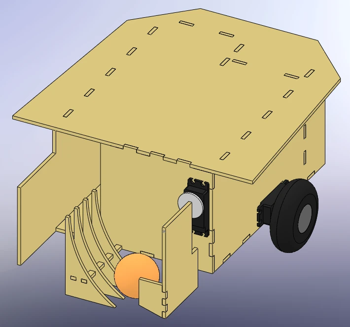
Grabbing the ball was initially planned out as a more complicated process involving two servos, one to move the ball into position and one to lift it up so as to be fired, as well as other gears and gear shafts. The final design is much more simplistic and just as effective, if not more so. This design involves only one servo that is directly attached to a wide paddle. Once the ball is somewhere in front of the robot, the paddle will swing down and capture the ball. A stopper is placed on the end of the paddle to make sure that the ball doesn’t roll out. The paddle then continues along its rotation and lifts the ball up a curved ramp. At the top of the ramp, the ball rolls out and into the loading compartment where it waits to be fired.
Launcher
The Launcher turned into the most electrically complicated of the actuation systems. The idea behind it was to use a solenoid to launch the ball from a stationary position on the ground to about 5 feet in the air where it could be easily grabbed. However, a couple issues had to be dealt with for this system to function properly. A solenoid is effectively a long conductive material that is looped many times around a free moving magnetic core. When current is passed through this conductive material, a magnetic field is induced inside the loop. The magnetic core then aligns with this induced field and is quickly pulled inward. A pin on the forward moving side of the core pushes through a hole in the solenoid and pops out, hitting anything in its way. However, during initial testing, I discovered that the solenoid wouldn’t be able to launch the ball high enough with a direct hit. To overcome this problem, I took the advice of our teacher Dr. Schwartz and created a mechanism as shown below.

The solenoid generated a large force (much larger than what was needed to move a hollow plastic ball), yet it couldn't generate enough speed to hit the ball high enough. By implementing the above ball batter, the force of the solenoid at the base of the batter was transformed into a torque, which was then transferred down the batter to the ball. Since the ball was much farther away from pivot point than the solenoid, the torque generated by the solenoid produced far less force at the ball’s location, yet would hit the ball much faster and transfer more speed to the ball than it would have if the ball were closer. In this way, the system traded force for speed, and the result was a ball that soared much higher (5 to 6 feet) than it would have otherwise.

Another problem was the fact that the solenoid drew a large amount of current when it was activated. If I were to power the solenoid directly from the battery source, this large spike in current could cause a momentary drop in voltage, possibly resetting important devices. Thus, I decided to use a 0.1 F capacitor to store up power and then release it through a series of relays. I also used a 50Ω resistor rated for 25W. The resistor was used to slow down the charge time of the capacitor so that not too much current was drained from the batteries at once. However, during the beginning of a charge, the capacitor could draw around 200mA, causing the resistor to consume about 2W. Although the normal resistors provided by the IMDL lab may have been able to handle this for a few seconds, I decided to err on the side of caution and use resistors that I knew would work.